-
Test Solutions
-
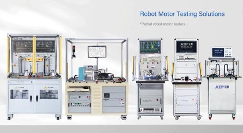
Robot Motor Test Solutions
Robot Motor Test Solutions
-
Electric Vehicle Motor Test Solutions
- AC induction motor stator tester
- Die-cast rotor tester
- BLDC motor stator tester
- Permanent magnetic rotor tester
- BLDC motor tester
Electric Vehicle Motor Test Solutions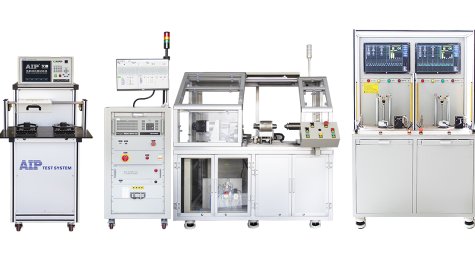
-
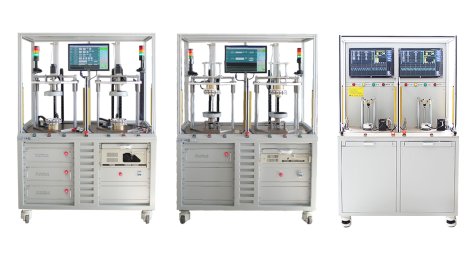
Electric Bike Motor Test Solutions
Electric Bike Motor Test Solutions
-
Automotive Motor Test Solutions
- AC induction motor stator tester
- Die-cast rotor tester
- BLDC motor stator tester
- Permanent magnetic rotor tester
- BLDC motor tester
Automotive Motor Test Solutions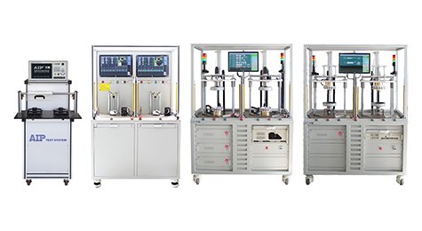
-
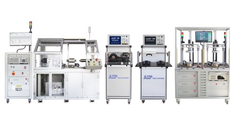
Motor automation test solutions
Motor automation test solutions
-
Air Conditioner Fan Motor Test Solutions
- AC induction motor stator tester
- Die-cast rotor tester
- AC motor tester
- BLDC motor stator tester
- Permanent magnetic rotor tester
- BLDC motor tester
Air Conditioner Fan Motor Test Solutions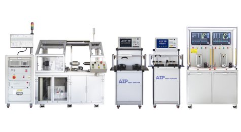
-
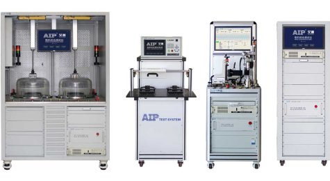
Fan Motor Test Solutions
Fan Motor Test Solutions
-
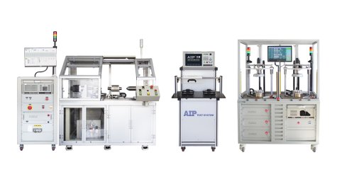
Compressor Motor Stator Test Solutions
Compressor Motor Stator Test Solutions
-
Washing Machine Motor Test Solutions
- AC induction motor stator tester
- Die-cast rotor tester
- AC motor tester
- BLDC motor stator tester
- Permanent magnetic rotor tester
- BLDC motor tester
- Single-phase/three-phase induction motor dynamometer tester
Washing Machine Motor Test Solutions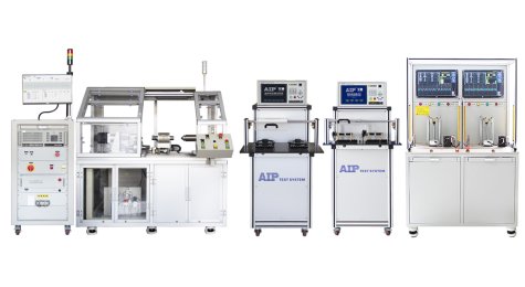
-
Power Tool Motor Test Solutions
- Armature tester
- BLDC motor stator tester
- Permanent magnetic rotor tester
- Cabinet safety tester
- Desktop safety tester
Power Tool Motor Test Solutions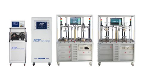
-
Small Appliance Motor Test Solutions
- AC induction motor stator tester
- Die-cast rotor tester
- AC motor tester
- Armature tester
- BLDC motor stator tester
- Permanent magnetic rotor tester
- BLDC motor tester
- AC power source
- DC motor dynamometer tester
- Single-phase/three-phase induction motor dynamometer tester
- Cabinet safety tester
- Desktop safety tester
Small Appliance Motor Test Solutions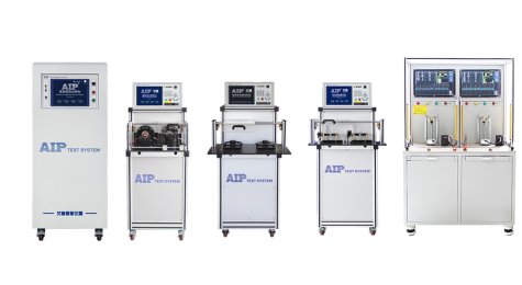
-
Industry Motor Test Solutions
- AC induction motor stator tester
- Die-cast rotor tester
- AC motor tester
- Single-phase/three-phase induction motor dynamometer tester
Industry Motor Test Solutions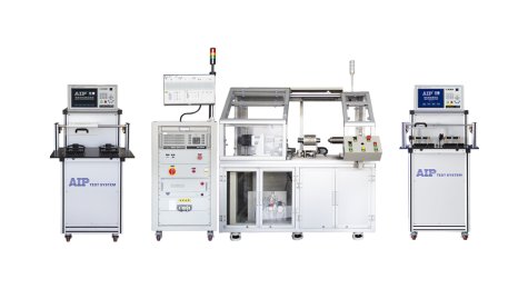
-
Pump Motor Test Solutions
- AC induction motor stator tester
- Die-cast rotor tester
- AC motor tester
- BLDC motor stator tester
- Permanent magnetic rotor tester
- BLDC motor tester
- Single-phase/three-phase induction motor dynamometer tester
Pump Motor Test Solutions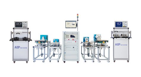
-
Blower Fan Motor Test Solutions
- AC induction motor stator tester
- AC motor tester
- BLDC motor stator tester
- Permanent magnetic rotor tester
- BLDC motor tester
- AC power source
- DC motor dynamometer tester
- Single-phase/three-phase induction motor dynamometer tester
- Cabinet safety tester
- Desktop safety tester
Blower Fan Motor Test Solutions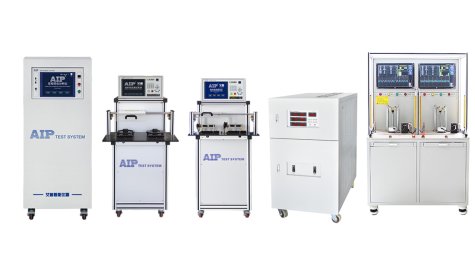
-
Servo Motor Test Solutions
- BLDC motor stator tester
- Permanent magnetic rotor tester
- BLDC motor tester
- DC motor dynamometer tester
Servo Motor Test Solutions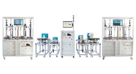
-
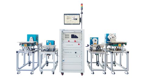
Dynamometer Test Solutions
Dynamometer Test Solutions
-
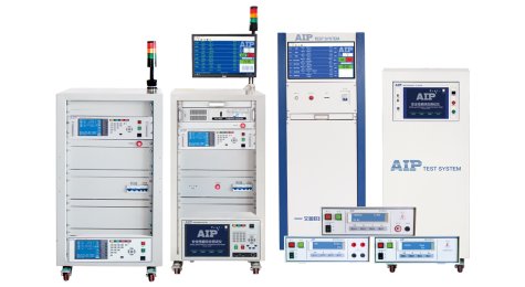
Safety Test Solution
Safety Test Solution
-
Robot Motor Test Solutions
-
Products
-
Stator Tester
- Partial discharge tester
- AC induction motor stator tester
- BLDC motor stator tester
- Stator back electromotive force (EMF) tester
- Automatic line applied stator tester
- Pinhole insulation tester
- Permanent magnet synchronous(PMSM) motor stator tester
- Universal motor stator tester
- Stator vacuum tester
- AC/DC hipot & insulation analyzer
Stator Tester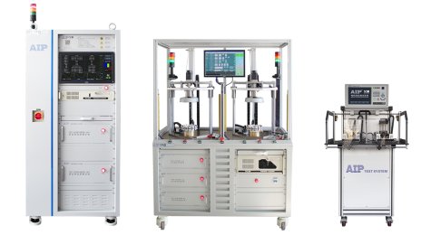
-
Rotor Tester
- Die-cast rotor tester
- Permanent magnetic rotor tester
- Permanent magnet synchronous motor rotor tester
- Automation line applied aluminum rotor tester
Rotor Tester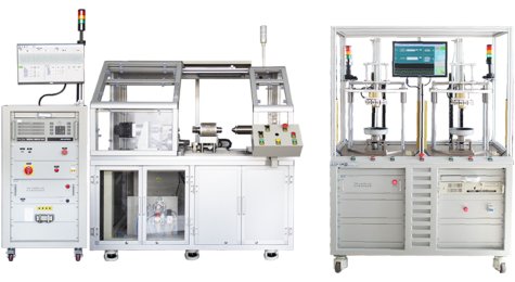
-
Electric Motor Tester
- Motor friction torque tester
- Motor cogging torque tester
- Motor performance tester
- AC motor tester
- BLDC motor tester
- BLDC motor load tester
- BLDC motor no load tester
- Permanent magnet synchronous motor tester
- Permanent magnet dc motor tester
- Universal motor tester
- EC motor tester
- Automation line applied motor tester
Electric Motor Tester
-
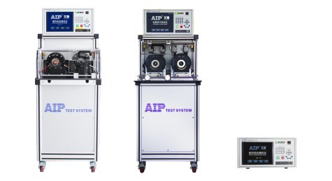
Armature Tester
Armature Tester
-
Dynamometer
- Electric dynamometer tester
- DC motor dynamometer tester
- Single-phase/three-phase induction motor dynamometer tester
Dynamometer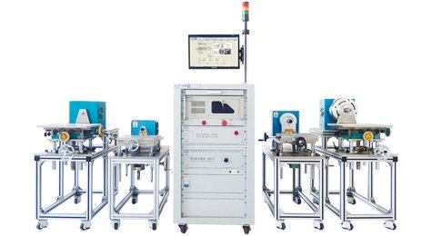
-
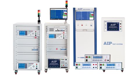
Safety Tester
Safety Tester
-
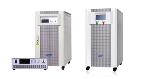
Power Source
Power Source
-
Coil tester
Coil tester

-
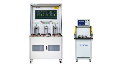
FCT
FCT
-
Stator Tester
- Technical Support
- News
- About Us
- Contact Us
一级标题
一级标题


